Introduction:
In the last
blog post, I demonstrated the usage of I2C protocol to build a communication channel between Infineon
CYW920835M2EVB evaluation board and
ESP32 Dev Kit MCU.
Today I want to to throw Bluetooth funtionality into the mix to control
the ESP32 built-in LED blinking frequency from a Bluetooth capable
smart device. The architecture of the system would be as follows:
- Infenion AIROC CYW920835 Evalboard will host a BLE GATT server with custom "LED"
service. In addition it will be acting as I2C master to communicate with
the ESP32.
- ESP32 DevKit acting as I2C peripheral and
waiting for commands from master to configure its onboard LED based on data written by a
Bluetooth user to the AIROC LED GATT service.
- A Bluetooth user would connect to the AIROC via smart device and have the ability to control the following features of the ESP32 built-in LED:
- LED status: On = 1, OFF = 0
- LED blinking period in seconds
- When the Bluetooth user pairs / connect successfully with the AIROC board. The yellow LED would be lid to indicate success of the Bluetooth connection. The LED would turn off when the Bluetooth connection drops. (e.g. Bluetooth user disconnects)
- The AIROC
board would save the pairing (bonding) information and last entered LED status and LED blinking period by the user in its non-volatile memory so it is still accessible after a power cycle.
Bluetooth Low Energy & GATT:
In our example we will use the embedded AIROC Bluetooth stack with the provided BTSDK to implement the Bluetooth functionlity of our app. We will use Bluetooth low energy technology (BLE) often used in low power smart devices for short-distance wireless communication. The BLE protocol archtecture is divided into multiple layers extending from hardware radio layer to the application layer as depicted below. In our application we are particulary interested in the "Generic Attribute Profile" GATT layer to implement and expose our "LED" control service.
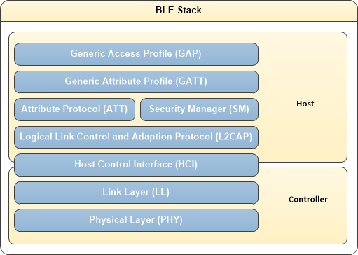 |
| https://infineon.github.io/bless/ble_api_reference_manual/html/page_ble_general.html |
The GATT layer constitues a framework that defines a collection of services. Each service in turn can have multiple characteristics which could be configured for various operations such as reading, writing data and also sending notifications upon subscription.
There are already many standard profiles with associated
services and characteristics that are defined by the Bluetooth SIG.
 |
| GATT Profile Hierachy: https://learn.adafruit.com/assets/13828 |
AIROC Bluetooth Application Code:
The source code for the application can be found under this Github repo. The provided code examples in the BTSDK were my starting point to understand how to write a simple Bluetooth application and use the I2C driver to communicate with a peripheral device (ESP32 in this case)
Defining custom GATT service and characterstics:
We start by defining the 16 bit UUIDs of our LED custom GATT service as shown below. The service contains two characterstics: one to configure the LED ON/OFF blinking status and one to confgiure the blinking period of the LED.
led_controller_uuid.h/** @file
*
* LE LED Controller UUID
*
* This file provides UUID definitions for LED Controller
*
*/
#ifndef _LED_UUID_H_
#define _LED_UUID_H_
/******************************************************************************
* Constants
******************************************************************************/
/* 16-bit UUID of the LED Controller Service */
#define UUID_LED_SERVICE 0x23, 0x20, 0x56, 0x7c, 0x05, 0xcf, 0x6e, 0xb4, 0xc3, 0x41, 0x77, 0x28, 0x51, 0x82, 0x7e, 0x1b
/* 16-bit UUID value of the LED Controller ON / OFF Characteristic Configuration */
#define UUID_LED_CHARACTERISTIC_ON_OFF_CONFIG 0x1a, 0x89, 0x07, 0x4a, 0x2f, 0x3b, 0x7e, 0xa6, 0x81, 0x44, 0x3f, 0xf9, 0xa8, 0xf2, 0x9b, 0x5e
/* 16-bit UUID value of the LED Controller Blink period Characteristic, Configuration */
#define UUID_LED_CHARACTERISTIC_BLINK_PERIOD_CONFIG 0x1b, 0x88, 0x06, 0x3a, 0x2e, 0x2b, 0x4e, 0xa5, 0x71, 0x33, 0x3a, 0xf7, 0xb8, 0xc2, 0x1b, 0x6e
#endif // _LED_UUID_H_
Next, we define the application GATT database which contain the mandatory GAP/GATT services for device identification and advertisting in additon to the custom LED service. As mentiond earlier, two readable/writable characterstics are defined such that LED blinking status and period could be configured from a GATT client (e.g my smartphone with nRF connect app upon connection with the AIROC board)
led_controller_main.c
/*
* This is the GATT database for the LED Controller application. It defines
* services, characteristics and descriptors supported. Each attribute in the database has a handle,
* (characteristic has two, one for characteristic itself, another for the value).
* The handles are used by the peer to access attributes, and can be used locally by application for
* example to retrieve data written by the peer. Definition of characteristics
* and descriptors has GATT Properties (read, write, notify...) but also has
* permissions which identify if and how peer is allowed to read or write
* into it. All handles do not need to be sequential, but need to be in
* ascending order.
*/
const uint8_t led_controller_gatt_database[]=
{
// Declare mandatory GATT service
PRIMARY_SERVICE_UUID16( HANDLE_HSENS_GATT_SERVICE, UUID_SERVICE_GATT ),
// Declare mandatory GAP service. Device Name and Appearance are mandatory
// characteristics of GAP service
PRIMARY_SERVICE_UUID16( HANDLE_HSENS_GAP_SERVICE, UUID_SERVICE_GAP ),
// Declare mandatory GAP service characteristic: Dev Name
CHARACTERISTIC_UUID16( HANDLE_HSENS_GAP_SERVICE_CHAR_DEV_NAME, HANDLE_HSENS_GAP_SERVICE_CHAR_DEV_NAME_VAL,
UUID_CHARACTERISTIC_DEVICE_NAME, GATTDB_CHAR_PROP_READ, GATTDB_PERM_READABLE ),
// Declare mandatory GAP service characteristic: Appearance
CHARACTERISTIC_UUID16( HANDLE_HSENS_GAP_SERVICE_CHAR_DEV_APPEARANCE, HANDLE_HSENS_GAP_SERVICE_CHAR_DEV_APPEARANCE_VAL,
UUID_CHARACTERISTIC_APPEARANCE, GATTDB_CHAR_PROP_READ, GATTDB_PERM_READABLE ),
// Declare proprietary LED Service with 128 byte UUID
PRIMARY_SERVICE_UUID128( HANDLE_HSENS_SERVICE, UUID_LED_SERVICE ),
// Declare characteristic LED Configuration
// The configuration consists of 1 byte which indicates target state of the LED
CHARACTERISTIC_UUID128_WRITABLE( HANDLE_HSENS_SERVICE_CHAR_LED_STATUS, HANDLE_HSENS_SERVICE_CHAR_LED_STATUS_VAL,
UUID_LED_CHARACTERISTIC_ON_OFF_CONFIG, GATTDB_CHAR_PROP_READ | GATTDB_CHAR_PROP_WRITE,
GATTDB_PERM_READABLE | GATTDB_PERM_WRITE_CMD | GATTDB_PERM_WRITE_REQ ),
// The configuration consists of 1 byte which indicates blink period of the LED in seconds
CHARACTERISTIC_UUID128_WRITABLE( HANDLE_HSENS_SERVICE_CHAR_LED_BLINK_PERIOD, HANDLE_HSENS_SERVICE_CHAR_LED_BLINK_PERIOD_VAL,
UUID_LED_CHARACTERISTIC_BLINK_PERIOD_CONFIG, GATTDB_CHAR_PROP_READ | GATTDB_CHAR_PROP_WRITE,
GATTDB_PERM_READABLE | GATTDB_PERM_WRITE_CMD | GATTDB_PERM_WRITE_REQ ),
// Declare Device info service
PRIMARY_SERVICE_UUID16( HANDLE_HSENS_DEV_INFO_SERVICE, UUID_SERVICE_DEVICE_INFORMATION ),
// Handle 0x4e: characteristic Manufacturer Name, handle 0x4f characteristic value
CHARACTERISTIC_UUID16( HANDLE_HSENS_DEV_INFO_SERVICE_CHAR_MFR_NAME, HANDLE_HSENS_DEV_INFO_SERVICE_CHAR_MFR_NAME_VAL,
UUID_CHARACTERISTIC_MANUFACTURER_NAME_STRING, GATTDB_CHAR_PROP_READ, GATTDB_PERM_READABLE ),
// Handle 0x50: characteristic Model Number, handle 0x51 characteristic value
CHARACTERISTIC_UUID16( HANDLE_HSENS_DEV_INFO_SERVICE_CHAR_MODEL_NUM, HANDLE_HSENS_DEV_INFO_SERVICE_CHAR_MODEL_NUM_VAL,
UUID_CHARACTERISTIC_MODEL_NUMBER_STRING, GATTDB_CHAR_PROP_READ, GATTDB_PERM_READABLE ),
// Handle 0x52: characteristic System ID, handle 0x53 characteristic value
CHARACTERISTIC_UUID16( HANDLE_HSENS_DEV_INFO_SERVICE_CHAR_SYSTEM_ID, HANDLE_HSENS_DEV_INFO_SERVICE_CHAR_SYSTEM_ID_VAL,
UUID_CHARACTERISTIC_SYSTEM_ID, GATTDB_CHAR_PROP_READ, GATTDB_PERM_READABLE ),
};
size_t led_controller_gatt_database_size = sizeof(led_controller_gatt_database);
uint8_t led_controller_device_name[] = DEV_NAME; //GAP Service characteristic Device Name
uint8_t led_controller_appearance_name[2] = { BIT16_TO_8(APPEARANCE_GENERIC_TAG) };
char led_controller_char_mfr_name_value[] = { 'C', 'y', 'p', 'r', 'e', 's', 's', 0, };
char led_controller_char_model_num_value[] = { '1', '2', '3', '4', 0, 0, 0, 0 };
uint8_t led_controller_char_system_id_value[] = { 0xbb, 0xb8, 0xa1, 0x80, 0x5f, 0x9f, 0x91, 0x71};
Now we declared the structure of our GATT server with required services and associated characterstics, we can use the BTSDK API functions to initialze the GATT database once the Bluetoott stack is up and running. The SDK also provides the possibility to register callback functions for GATT related events (e.g. read / write request) which will be essential to handle incoming configurations for our LED service. You can refer to the "wiced_bt_gatt_db_init" and "wiced_bt_gatt_register" documentation for the details.
led_controller_gatt.c
/*
* helper function to init GATT
*
*/
void led_controller_gatt_init()
{
wiced_bt_gatt_status_t gatt_status;
/* Register with stack to receive GATT callback */
gatt_status = wiced_bt_gatt_register(led_controller_gatts_callback);
WICED_BT_TRACE( "wiced_bt_gatt_register: %d\n", gatt_status );
/* Tell stack to use our GATT database */
gatt_status = wiced_bt_gatt_db_init( led_controller_gatt_database, led_controller_gatt_database_size );
WICED_BT_TRACE("wiced_bt_gatt_db_init %d\n", gatt_status);
}
Other than initializing the GATT database, we need to make some API calls so our device is Bluetooth advertising and can recieve pairing and connection requests from a Bluetooth client device. Our initialization function eventually become as below. This function is then registed in our application entry point (i.e. main function) as part of the Bluetooth managment callbak function which eventually trigges at different Bluetooth events reported by the Bluetooth stack.
led_controller_gatt.c
/*
* This function is executed in the BTM_ENABLED_EVT management callback.
*/
void led_controller_application_init( void )
{
wiced_result_t result;
WICED_BT_TRACE("led_controller_application_init\n" );
// init gatt
led_controller_gatt_init();
/* Load previous paired keys for address resolution */
led_controller_load_keys_for_address_resolution();
/* Allow peer to pair */
wiced_bt_set_pairable_mode(WICED_TRUE, 0);
/* Set the advertising params and make the device discoverable */
led_controller_set_advertisement_data();
result = wiced_bt_start_advertisements( BTM_BLE_ADVERT_UNDIRECTED_HIGH, 0, NULL );
WICED_BT_TRACE( "wiced_bt_start_advertisements %d\n", result );
/*
* Set flag_stay_connected to remain connected after all messages are sent
* Reset flag to 0, to disconnect
*/
led_controller_state.flag_stay_connected = 1;
}
After taking care of the Bluetooth part we need to create the logic of our I2C master that it performs write requests to the ESP32 (our I2C peripheral) when the user write values into our LED GATT service characterstics. We start by defining some I2C constants such as the peripheral address and the I2C commands IDs for LED control. These definitions need to match on the peripheral application code as we will see later.
led_i2c_slave.h
/** @file
*
* ESP 32 I2C LED Control Interface
*
* This file provides I2C definitions for ESP32 slave device to control its built-in LED on GPIO5 (DevKit C)
*
*/
#ifndef _ESP32_I2C_H_
#define _ESP32_I2C_H_
/******************************************************************************
* Constants
******************************************************************************/
/* I2C identification address of the ESP32 */
#define ESP32_I2C_ADDRESS 0x25
/* I2C command to turn on ESP32 built-in LED on GPIO5 */
#define LED_ON_COMMAND 0x10
/* I2C command to turn off ESP32 built-in LED on GPIO5 */
#define LED_OFF_COMMAND 0x20
/* I2C command to set the blinking period of the LED */
#define LED_SET_BLINK_PERIOD_COMMAND 0x30
#endif // _ESP32_I2C_H_
The I2C communication comes into play in two areas of the code on the master side. First at application initilization where we read the stored LED configuration from NVRAM and send it over I2C to the ESP32. The second area is where the LED characterstics defined earlier get written by a GATT client then the LED state and blink period values get eventually transferred via I2C to the ESP32. At the same time, the new written configuration is saved into NVRAM on the master side so it could be reused when the application reboots and sent again to the ESP32 during initilizatin phase. For trasnferring the I2C data a two bytes sized array is declared as a write buffer. The first byte is the command ID and the second byte will be used to write the blink period value to the ESP32 (i.e. second byte is only important for the "LED_SET_BLINK_PERIOD_COMMAND"). The code snippets below reflect this.
led_controller_main.c
/*
* Entry point to the application. Set device configuration and start BT
* stack initialization. The actual application initialization will happen
* when stack reports that Bluetooth device is ready.
*/
APPLICATION_START( )
{
WICED_BT_TRACE("BLE LED Controller Start\n" );
// Assign AIROC LED 1 GPIO
led_pin = LED_1_GPIO;
wiced_transport_init( &transport_cfg );
// Set to PUART to see traces on peripheral uart(puart)
wiced_set_debug_uart( WICED_ROUTE_DEBUG_TO_PUART );
wiced_bt_stack_init(led_controller_management_cback, &wiced_bt_cfg_settings, wiced_bt_cfg_buf_pools);
// start I2C on dedicated SCL, SDA pins
WICED_BT_TRACE("Init I2C\n");
wiced_hal_i2c_init();
wiced_hal_i2c_select_pads(I2C_SCL, I2C_SDA);
// read last stored controller info from NVRAM
wiced_result_t result;
wiced_hal_read_nvram(LED_CONTROLLER_VS_ID, sizeof(led_controller_hostinfo), (uint8_t*)&led_controller_hostinfo, &result);
// set initial state, blink period of the LED based on stored data from NVRAM
led_controller_set_led_state(led_controller_hostinfo.led_status);
led_controller_set_led_blink_period(led_controller_hostinfo.led_blink_period_sec);
}
led_controller_gatt.c
/*
* Process write request or write command from peer device
*/
wiced_bt_gatt_status_t led_controller_gatts_req_write_handler( uint16_t conn_id, wiced_bt_gatt_write_t * p_data )
{
wiced_bt_gatt_status_t result = WICED_BT_GATT_SUCCESS;
uint8_t *p_attr = p_data->p_val;
uint8_t nv_update = WICED_FALSE;
WICED_BT_TRACE("write_handler: conn_id:%d hdl:0x%x prep:%d offset:%d len:%d\n ", conn_id, p_data->handle, p_data->is_prep, p_data->offset, p_data->val_len );
switch ( p_data->handle )
{
case HANDLE_HSENS_SERVICE_CHAR_LED_STATUS_VAL:
if ( p_data->val_len != 1 )
{
return WICED_BT_GATT_INVALID_ATTR_LEN;
}
led_controller_hostinfo.led_status = p_attr[0];
WICED_BT_TRACE( "led_controller_write_handler:led status: %d\n", led_controller_hostinfo.led_status );
led_controller_set_led_state(led_controller_hostinfo.led_status);
nv_update = WICED_TRUE;
break;
case HANDLE_HSENS_SERVICE_CHAR_LED_BLINK_PERIOD_VAL:
if ( p_data->val_len != 1 )
{
return WICED_BT_GATT_INVALID_ATTR_LEN;
}
led_controller_hostinfo.led_blink_period_sec = p_attr[0];
WICED_BT_TRACE( "led_controller_write_handler:led blink period: %d\n", led_controller_hostinfo.led_blink_period_sec);
led_controller_set_led_blink_period(led_controller_hostinfo.led_blink_period_sec);
nv_update = WICED_TRUE;
break;
default:
result = WICED_BT_GATT_INVALID_HANDLE;
break;
}
if ( nv_update )
{
wiced_result_t rc;
int bytes_written = wiced_hal_write_nvram( LED_CONTROLLER_VS_ID, sizeof(led_controller_hostinfo), (uint8_t*)&led_controller_hostinfo, &rc );
WICED_BT_TRACE("NVRAM write:%d rc:%d", bytes_written, rc);
}
return result;
}
led_controller_main.c
/**
* Set the LED status by making I2C write to ESP32
*/
void led_controller_set_led_state(uint8_t led_state)
{
if(led_state == 0){
write_buffer[0] = LED_OFF_COMMAND;
WICED_BT_TRACE("Send LED OFF Command: %0x\n", LED_OFF_COMMAND);
wiced_hal_i2c_write((uint8_t*)&write_buffer, sizeof(write_buffer), ESP32_I2C_ADDRESS);
}
else if (led_state == 1)
{
write_buffer[0] = LED_ON_COMMAND;
WICED_BT_TRACE("Send LED ON Command: %0x\n", LED_ON_COMMAND);
wiced_hal_i2c_write((uint8_t*)&write_buffer, sizeof(write_buffer), ESP32_I2C_ADDRESS);
}
else
{
WICED_BT_TRACE("INVALID LED STATE: %d\n", led_state);
}
}
/**
* Set the LED blink period by making I2C write to ESP32
*/
void led_controller_set_led_blink_period(uint8_t led_blink_period_sec)
{
if(led_blink_period_sec != 0)
{
write_buffer[0] = LED_SET_BLINK_PERIOD_COMMAND;
write_buffer[1] = led_blink_period_sec;
WICED_BT_TRACE("Send LED SET BLINK PERIOD Command: %0x\n", LED_SET_BLINK_PERIOD_COMMAND);
wiced_hal_i2c_write((uint8_t*)&write_buffer, sizeof(write_buffer), ESP32_I2C_ADDRESS);
}
else
{
WICED_BT_TRACE("INVALID LED BLINK PERIOD: %d\n", led_blink_period_sec);
}
}
ESP32 I2C Peripheral Application Code:
The ESP32 application code will be much simpler. We just need to create a simple I2C peripheral which will reciever a predfined set of I2C command and toggle the ESP32 onboard LED based on that. To control the blinking period of the ESP32 accurately, the ESP32 high precision timer is used. I will not go through all the bits and pieces of the ESP32 application code, instead I will just put a snippet below of the I2C peripheral state machine task code. The task basically waits for a write request and fetches the command ID (first byte) from the recieved buffer. In case of ON/OFF command it simply starts / stops the LED timer respectively. In case of LED blink period command, the value from the second byte of the buffer is used to set the new LED timer period. If the timer is already running it is simply restarted with the new period.
static void i2c_slave_task(void *arg)
{
i2c_slave_context_t *context = (i2c_slave_context_t *)arg;
esp_timer_handle_t timer = (esp_timer_handle_t)context->timer;
while (true) {
i2c_slave_event_t evt;
if (xQueueReceive(context->event_queue, &evt, 10) == pdTRUE) {
if (evt == I2C_SLAVE_EVT_RX) {
switch (context->command_data[0]) {
case LED_ON_COMMAND:
ESP_LOGI(TAG, "LED_ON_COMMAND");
if (esp_timer_is_active(timer) == true)
{
ESP_LOGI(TAG, "LED_TIMER_ALREADY_RUNNING");
}
else
{
ESP_ERROR_CHECK(esp_timer_start_periodic(timer, led_blink_period_u_sec));
}
break;
case LED_OFF_COMMAND:
ESP_LOGI(TAG, "LED_OFF_COMMAND");
if (esp_timer_is_active(timer) == true)
{
ESP_ERROR_CHECK(esp_timer_stop(timer));
s_led_state = 0;
blink_led();
}
else
{
ESP_LOGI(TAG, "LED_TIMER_ALREADY_STOPPED");
}
break;
case LED_SET_BLINK_PERIOD_COMMAND:
ESP_LOGI(TAG, "LED_SET_BLINK_PERIOD_COMMAND with period of: %d seconds", context->command_data[1]);
led_blink_period_u_sec = 1000000 * context->command_data[1];
if (esp_timer_is_active(timer) == true)
{
ESP_LOGI(TAG, "Restarting LED Timer");
ESP_ERROR_CHECK(esp_timer_stop(timer));
ESP_ERROR_CHECK(esp_timer_start_periodic(timer, led_blink_period_u_sec));
}
break;
default:
ESP_LOGE(TAG, "Invalid command");
break;
}
}
}
}
vTaskDelete(NULL);
}
Testing it All Together:
To test the overall logic of the application, I divided it into smaller test steps such that we can incrementally verify the behavior of our system as explained below:
Test application initilization state:
This is the simplest sanity test to check our BLE application on the AIROC side boots, it starts Bluetooth advertising and writes a default LED configuration succesfully via I2C to the ESP32. By inspecting the UART logs for the AIROC board, I was able to confirm that the Bluetooth stack is up and running and the GATT server startup successds indicated by a return code of zero. Regarding I2C, it seems that the driver got initilized and sent LED OFF command at startup since the default values read from NVRAM is zero. For the blink period command, we recieve a warning message that zero is not valid value which is totally fine as per the design of the application and we expect nothing to be sent to ESP32. To confirm the I2C communication actually tooke place we also inspect the ESP32 application startup logs and we see that it indeed only recieved the LED OFF command. Since the ESP32 application by default starts without starting the blinking timer, the LED is already OFF as indicated by the logs.
 |
| Infenion AIROC Bluetooth LE application startup logs |
 |
| ESP32 I2C peripheral application startup logs |
Test BLE pairing and connection with AIROC board:
The next was about establishing a Bluetooth BLE connection with the board using a Google Pixel smartphone and read the GATT profile services using the nRF connect Android app. I was able eventually to pair and connect to the AIROC board without any issues. Upon pairing, I was able to read bonding success messages from the application logs and also the AIRCO user yellow LED was behaving as expected upon connecting and disconnecting the board via Bluetooth. Through the nRF connect app, I was able to find my custom defined LED service with its two defined characterstics. Great we are almost there :)
Test Controlling of LED states and blink period from AIROC GATT LED service :
Finally the moment of truth. We will test the application full communication path (GATT BLE -> I2C -> ESP32 timer -> driving of the LED). To trigger this all we have to do is write the LED state characterstic and LED blink period characterstic from the nRF connect app while connected to the AIROC and observed the ESP32 logs and timer status. First when setting the first characterstic in the list above to the value one, I could observed the ESP32 LED starting to blink every second we can confirm this with the application logs as shown below:
 |
| ESP32 LED On command triggered upon GATT write request and timer blinking the LED every 1 second |
When setting the LED status characterstic to zero in the nRF connect app. The timer stops as expected and LED blinking as a result.
Finally I set the LED status characterstic to value one again and attempted to set the blinking period characterstic value to five such that the LED will blink every fives seconds instead of one second as show below
Is not that great we built an entire end to end solution using Bluetooth, timers and I2C to control an LED :). Feel free to try it out and let me know how it went


